The engine.
The last Mini I owned had a 1275 turbo from a Metro Turbo. But I always fancied a 16v head after seeing a KAD 16 head at a show. The cost put me off though, and I knew that somewhere someone had built a motorbike cylinder head onto the A-series block.


Sourcing the engine
Finding the 1275 motor was the first challenge. But again this was found locally, half buried in a shed in a field.
After finding the project shell and engine, I knew that I had to build a 16v engine. A short internet search lead me to Specialist Components website and the fairly well known BMW head conversion.
I ordered their manual and set about plans to build myself the engine I wanted.

Sourcing the head
Finding the head was simple enough on eBay. I'm always looking for a bargain so I don't want to buy the most expensive parts I can find. I know there are different cams available in the BMW head, but I was happy to settle for whatever cams I could find. To me, it's not about achieving maximum power, it's about the building process. I do things because I can.

The block
The block was stripped bare and checked over. the head steady bolt had been snapped and drilled out poorly to the next size, but apart from that, it seemed all good. I started by blanking all the holes in the block that were no longer required and sent the block off for machining.
The engine was bored out to +60" and new cam bearings fitted. New pistons and bearings were also supplied.
My original intention was to run an open block with the coolant passing through the head gasket. But eventually I changed my mind and dry decked it as so many others have.

Early attempts
I have an annoying trait that I believe that if someone else can do something, then I can learn. So I set about making the adaptor plates myself using the tools and knowledge I had.
Early attempts required a plate with holes cut with a hole cutter and adjustable plates bolted on to hold seal. This would have worked, but would not have looked fantastic.
I had to try a different route to make this better.

The world of 3D printing

For a long time, I have been able to use basic CAD packages to design what I need, but having it made was a different problem. So I went to learn how to use newer CAD packages and quickly moved from Solidworks to Fusion 360.
Having full access to these programs through work and experienced staff for guidance, I was then able to design anything I wanted. 3D printing then allows me to make these parts at low cost to try them out for fit and function. This new world of making plastic parts for trials is fantastic. All parts I make are printed and trialled before making from metal.
3D materials
Whilst most of the material used for 3D printing is PLA, different materials can be printed. PLA is cheap and easy to print which makes it ideal for templates, but it does have its drawbacks. It will start to go soft at around 50 degrees C.
There are other materials available that will take a higher temperature and withstand being in an engine bay. I may use this for brackets etc, but also possibly to make the intake manifold.
All printing is done at home so I can make parts overnight to try the next day.

Machining
Plastic parts are great and easy to make. But making them from aluminium is a different game altogether. Luckily we have the equipment in work, it just required someone to show me how to use it,
After spending some time over the summer break learning how to use the machines, aluminium plates were made to replace the plastic ones. With these fitted, time to make brackets etc.


Mounting the end plates
Because everything was 3D printed and test fitted, I knew that the machined parts would fit.
Here it is mounted complete with water pump and crank pulley. These are to be changed in later designs to a different bottom pulley and electric water pump
Head gasket
This is a critical part, so how do I go about making it?
Would a copper sheet cut to shape and annealed do?
In the end, I contacted a company and had this made to my design. Its 1mm thick but compressed down to 0.6mm. What did surprise me though, the copper part is not fixed to the rest. Not really a problem I hope.


Head bolts
The bolts you see in the image above are original mini head studs, I have plenty. Apparently they are good enough to do the job, but I decided to go for ARP bolts.
With some research and a visit to the ARP stand at the NEC, i managed to work out which parts I would need to make a kit. I phoned a supplier (Kent cams) and gave them the list. Straight away the salesman realised what they were for and said "We do a kit for that!"

Scary rocker cover
A rocker cover does not sound scary, but when the billet is £200 and your new to machining, it's a bit worrying.
It took me three days to machine this, errors were made and corrected, and just on the last pass, it took a chunk out of the top near the centre!
The coil cover plate was then modified to cover the damage and now it is classed as a feature!
It is a bit heavy to be honest. The walls are 8mm thick, which is down to the design. I could make it thinner, but changing other feature before doing that is best. The next one will be better.
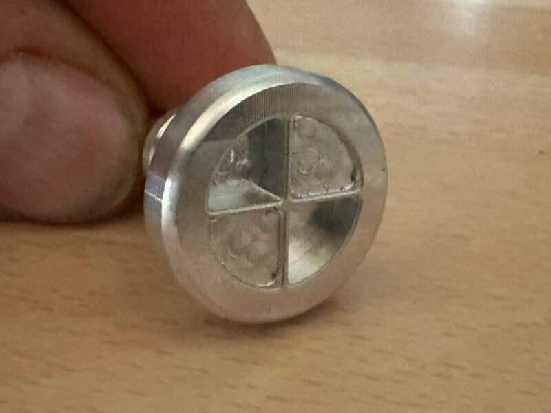

I don't know if these were a joke, but someone posted online about BMW making bolts that could not be undone without special tools that looked like their badge.
I thought it would be fun to make that into a reality, so these are the rocker cover bolts. I have made a tool to fit them and a torque wrench can be used to tighten them.

Managing the oil
A crucial part of the fitting of this head is the draining of the oil back to the sump. Two fittings are standard by most people into the bottom of the head down to the fuel pump hole, and a third from the top front plate. I wanted them to be in braided hose, but this makes it a little tricky. I machined a manifold to accept three fittings into the top of it, and one on the face. I'm happy with the ones from the head, but the end plate one is too close to the belt, a change or two is needed there. Oil is fed to the head by an external pipe to the top left rear of the head.
The gearbox already has a centre pick up pipe, and a second sump plug was fabricated into the rear of the gearbox to catch any metal particles on their way up to the engine. Care had to be taken that this plug does not obstruct oil flow, so a block was made so that the tip of the plug was just at the edge of the oil flow.
Create Your Own Website With Webador